Metal roofing
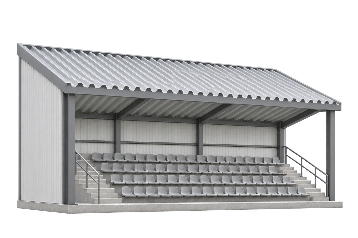
A substitute steel deck for a grandstand roof. How do you review the supplier’s proposal?
A supplier can deliver an alternative profile sooner for a grandstand canopy. To assess the change, the structural engineer needs the proposed deck section, its support conditions and data for its actual orientation. Matching rib height still leaves questions about flange widths, steel thickness, fixings and allowable deflection. This guide explains how to compare those details with the design and document the decision. The example concerns a load-bearing steel deck supporting further roof layers. Its specified function on the particular stand determines what the review needs to cover.
Locate the proposed change on the plan
Identify the structural grid lines and mark the limits of the proposed substitution. If it applies only to an extension over the last seating section, highlight the interface with the original roof. That junction can then be reviewed even where the rest of the roof has a regular layout.
Compare both cross-sections in their installed orientation
Attach section drawings for the specified and proposed products. On each, mark the face seen from the seats, rib direction and wide flange position. A thumbnail rotated on the quotation can obscure a difference in how the deck bears on the purlin.
Alongside profile depth, record rib pitch, effective cover width, the thickness specified in the table and the steel grade. Add whether the deck is solid or perforated. This identifies the exact variant when one trade name covers several gauges and finishes.
Match the load table to the support arrangement
Transfer the spans from the structural section and mark the actual sheet ends. Three support lines could represent one sheet continuous over two spans or two separate sheets meeting on the middle support. The joint arrangement determines which model the engineer needs to assess.
Look up the assumed bearing widths in the alternative deck’s table. End and intermediate supports can have different conditions. If the steel detail provides less bearing than the document assumes, flag the location for calculation or revision of the detail.
Check load directions and deflection
On the load sketch, draw the direction arrow and identify the top face of the profile. The engineer can then match downward and uplift cases to the product data. For an open stand, include the geometry of the open sides and roof edges.
Read the table heading to see whether a figure relates to resistance or to the load at a specified deflection limit. Include the heading and footnotes when sending an extract. They help the engineer check the deck and the other roof layers against the deformation limits specified for the assembly.
Coordinate fasteners and interfaces with other materials
A change in rib pitch can move the locations available for fasteners. On the support detail, show the flange positions of both profiles relative to the supporting steelwork. The engineer can check whether the required connections can be made and issue the appropriate installation detail.
At rooflights, perimeter flashings and service penetrations, mark the dimension that must suit the new profile. If a matching rib closure is unavailable, allow for developing and procuring that detail when comparing delivery dates.
Tie approval to the quotation revision
The approval record should identify the model, gauge, installation area, orientation and drawing revision. Where the substitute is accepted for part of the roof, carry its boundaries into the order and bundle label so the sheets reach the correct seating section.
At delivery, compare the pack identifier with the variant signed off by the engineer. A further change of gauge or perforation calls for updating the documents for that item. A complete drawing record will later identify the deck actually installed above each section.
7 branches. Materials closer to your project.