Designing the building envelope
Planning the supports for a mineral wool sandwich panel wall
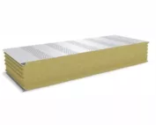
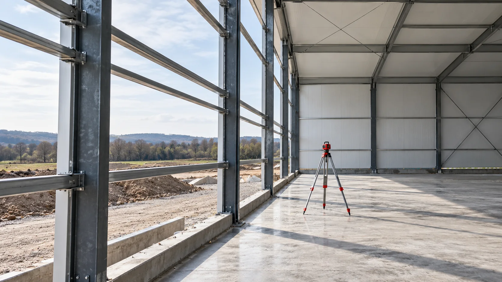
An insulated panel with a mineral wool core is a building envelope element that requires designed supports. Their arrangement is determined by loads, installation direction, openings and the properties of the specific panel. In a new hall, it is worth resolving these issues before ordering the frame. Adding rails later may conflict with windows, services and the façade line. Columns and rails transfer actions to further building elements. The insulated panel acts between supports within the range specified for the product; it should not automatically be treated as bracing for the entire hall. If the structural engineer wishes to utilise a specific interaction between the envelope and the frame, this must be justified in the design.
Define the role of the main frame
The frame should be stable in every planned construction phase. The sequence of wall cladding can change the effect of wind on the unfinished structure. Therefore, the installation organisation and temporary protection require agreement with the person responsible for the structure.
Match supports to panel orientation
Vertically oriented panels usually bear on horizontal members, and a horizontal layout requires supports aligned with the panel’s working direction. This is a general principle for organising the design, not a ready-made spacing. In both variants, the support widths and the fixing location must be checked.
The production length is not the same as the permissible span. A panel may pass over several supports, creating a different scheme from a single span. The selected load table must correspond to the actual arrangement. Values from single-span and multi-span tables must not be combined.
Plan openings as part of the structure
A gate removes a section of the wall field and changes the points where loads are transferred. The lintel, the posts at the opening and the support of the cut panels must be planned in advance. Simply screwing on a wide cover trim does not create a load-bearing frame for the cladding.
Agree the requirements of the window/door supplier and the gate mechanism. The panel should not accidentally carry the weight of guides or equipment for which it was not designed. With window bands, it is also important whether the narrow panel sections above and below the glazing have correct support.
Resolve the junction between the wall and the deflecting roof
In a new hall, an internal wall may reach the roof structure, which changes position under load. A rigid connection made without analysis may transfer forces to the panel that were not previously accounted for. Therefore, the top termination should not be resolved only when fitting the last section of the panel.
The structural engineer and the envelope designer should establish the range of movement and a detail that maintains the required functions. If the partition also has a fire or acoustic function, the method of accommodating displacement must remain compatible with it. Such a junction shows why the load-bearing capacity of the purlin alone does not describe the correctness of the entire wall support.

Check deflections, not just load-bearing capacity
The structure may be sufficiently strong, but its deflection will be unfavourable for the seams, flashings or airtightness. Therefore, the permissible displacements of the supports and the method of accommodating movements at the roof must be agreed. The wall should not be compressed by the descending roof structure.
Similarly, the thermal expansion of the cladding must be considered, especially with long dark panels. The choice of colour affects the temperature assumptions in the calculations. Introducing a darker façade after the purlins have been designed requires checking whether the earlier variant is still suitable.
Ensure the plane and durability of the supports
Before starting the envelope, check the axes, verticals and horizontals of the supports. Deviations should be within the range required by the design and the panel system. Levelling the structure by forced pressure on the panel may damage the core or leave permanent unevenness on the façade.
The coating of the supports should match the environment, and cut and welded areas require proper protection. In damp zones, pay attention to geometry that could retain water. Once the wall is closed, access to some surfaces of the structure will be limited.
Finish the coordination with a support map
On the shop drawing, show every line of support and the direction of installation, not only the main columns. Include panel and connection markings, the point of transfer of self-weight and the fixing zones. The details at the base must correspond to the behaviour assumed for the given system.
Once the layout is approved, a length list and lifting plan can be prepared. If the panel type changes, return to checking the tables and connections. Matching thickness does not prove matching load-bearing capacity. A well-coordinated structure allows the advantages of prefabrication to be used without improvised modification of the wall.
Questions and answers
Does a steel structure have to be provided under mineral wool panels?
Not always. Other substrates and arrangements are possible if the supports and fixings are suitably designed. However, the requirements of the specific product and substrate must be checked.
Will a thicker board allow some of the battens to be removed?
Sometimes this variant is possible, but it requires recalculation of loads, deflections, connections and fire requirements. The new spacing cannot be determined from the difference in thickness alone.
7 branches. Materials closer to your project.