Designing the envelope
How to determine the spacing of wall supports when wind acts unevenly?
A single support spacing does not suit every wall made of sandwich panels. Wind acts differently on the centre of the façade, the corner and a building with a large open gate. Colour, cladding and the arrangement of bays also come into play. The spacing must be determined for the specific panel and building conditions, then coordinated with its openings. The designer needs the location, dimensions and height of the building, the roof geometry and information about the surroundings. Large openings and the conditions under which they may remain open also matter. These data yield the external and internal actions needed to verify the envelope.
Gather data on the building and surroundings
Do not transfer the spacing from a similar hall in a different location. A similar area and the same colour do not mean the same loads. Even on one project, different walls may have different conditions. The zone plan should form a clear part of the input data for the selection.
Distinguish pressure and suction
Wind can press the panel against the supports or pull it away from the structure. Under suction, the connections are particularly important, and local loads near the edges may be greater than on the rest of the field. It is therefore not permissible to check only the behaviour of the panel under pressure.
The selection covers the panel, fasteners and supports. If one of these elements has insufficient load-bearing capacity or stiffness, a better result from the others alone does not solve the problem. It is worth establishing straight away whether the demanding zones will have a denser frame, different fixing or a different panel configuration.
A large open gate changes the envelope conditions
In the hall design, it must be established how internal pressure and possible open states of large openings have been taken into account. It should not be assumed independently that the gate will always be closed during wind. The way the building is used and the required design scenarios must be agreed with the designer.
The construction stage, when some walls do not yet exist, is also important. The final scheme does not have to describe all assembly conditions. The enclosure closure plan should take into account the stability of the structure and temporary actions. This makes it possible to distinguish the support spacing required in the completed building from the organisation of safe execution of successive fields.
Choose the table that matches the actual arrangement
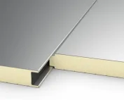
The type and thickness of the core, the thicknesses of both facings, the type of joint and the single- or multi-span scheme are required. The tables may additionally differentiate colour and temperature conditions. A more favourable value cannot be selected from a table intended for a different arrangement.
Also check how the span and the width of the supports are defined. The total length of the panel may include several spans and end sections beyond the support axis. The production value from the data sheet does not state how far the panel may span without support. These two pieces of information have separate applications.

Verify load-bearing capacity and serviceability
The limitation may be load-bearing capacity or deflection affecting appearance, tightness and interaction with flashings. The conditions indicated in the table and the relevant combinations of actions must be checked. Not every mechanically permissible arrangement will be suitable for demanding joinery or a high-quality façade appearance.
Thermal action is particularly important with dark and long panels. A change of colour after the wall has been designed may require re-verification. It should not be treated solely as a visual correction, especially on a heavily sun-exposed façade.
Relate supports to windows and gates
The arrangement of openings may interrupt the continuity of the panel or create short sections with a different scheme. Lintels and posts should provide the intended support and space for fasteners. Cutting a piece of the panel on site does not automatically preserve the properties of the full element.
In a new project, it is worth considering an adjustment to the façade layout before the frame is built. A logical position of openings and joints can reduce the number of additional rails. However, the saving must be demonstrated in the complete arrangement, not achieved by omitting a required support.
Transfer the result to the construction drawing
The final plan should show the axes and widths of supports, panel designations and fixing zones. Include the required tolerances and the method of checking flatness. If the design permits an alternative panel, it should have a defined configuration and verified conditions of use.
Before installation, compare the actual structure with the drawing. A change in the position of a rail affects the behaviour of the panel and the number of fasteners. The contractor should not compensate for such a difference with a random additional screw. The deviation requires assessment before it is concealed by the cladding.
Questions and answers
Does a thickness of 100 mm allow a fixed support spacing to be specified?
No. Loads, span layout, claddings, colour, interlock and connections are also needed. Thickness alone does not provide a sufficient basis for calculations.
Will a denser frame always solve the problem?
It may reduce the panel span, but the connections, support widths and the behaviour of the whole structure still need to be checked. Additional supports should result from an agreed solution.
7 branches. Materials closer to your project.