Maintenance and durability
Planning a roof covering replacement step by step
Begin by checking what actually needs replacing, not by choosing the new material. Inspect the covering, flashings, gutters, substructure and visible parts of the roof trusses, looking for leak causes and signs of persistent moisture. Assess whether the wear is local or affects the entire roof slope, as this shapes the scope of work. Only then compare coverings using real dimensions, set the schedule, protect the building, check the substrate, lay the new layers and hand over the roof with documentation.
Step 1. Determine what actually needs replacing
The survey should cover the covering, flashings, gutters, substructure and accessible parts of the roof truss. It looks for sources of leaks and signs of persistent damp. A distinction must be made between local wear and a problem affecting the whole roof slope. Sometimes repairing a detail is enough, and sometimes a larger part of the roof has to be removed.
It is worth defining the future use of the attic straight away. The conversion plan affects the insulation, windows and ventilation. If photovoltaics are planned, their loads and mounting must be taken into account. Designing these elements only after the renovation leads to renewed intervention in the new surface.
Check the formal requirements applicable to the scope of the investment. They may depend on the type of changes and the condition of the building. If the old covering contains asbestos, its removal requires separate organisation and a specialist company. Such material must not be treated as ordinary renovation waste.
Step 2. Compare coverings on actual dimensions
The measurement covers the lengths of the roof slopes, the eaves, ridges, roof valleys and all penetrations. The floor area of the house is not the roof area. Old drawings, too, may not reflect the built form. Accurate data make it possible to lay out cut sheets or modules and to anticipate where cutting will be needed.
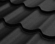
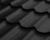
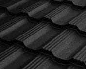
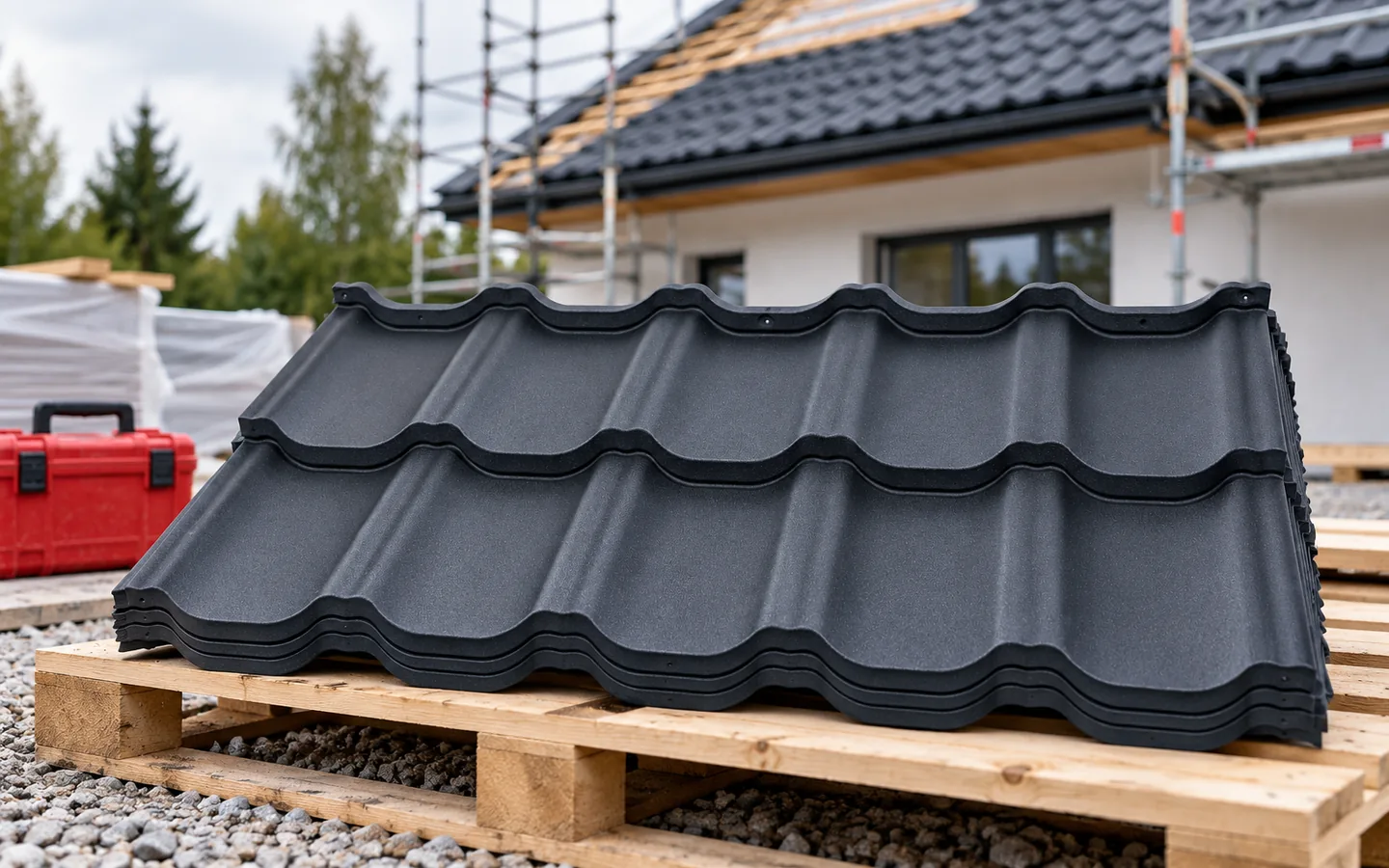
On a simple roof, it is worth comparing cut tile-effect metal roofing with modular tile-effect metal roofing. On an outbuilding, T18 or T35 trapezoidal sheeting can be considered, and in a heated workshop a roof sandwich panel. Each variant must suit the pitch and the structure. A new covering must not be chosen without checking whether the existing supports can be adapted to it.
A joint cost estimate should cover an identical scope. Include materials, flashings, fastenings, insulation, transport and installation. Add demolition and possible repairs to the substrate. The price of the basic steel sheet does not show the cost of the completed renovation.
Step 3. Agree the schedule and protection of the building
Deliveries and dismantling must be coordinated with the team’s readiness and the weather. A storage area should be prepared for the material. Long sheets require proper support and a carrying route. For sandwich panels, lifting equipment may be needed. These points should be settled before the transport arrives.
The work can be divided into stages if the structure and the adopted technology allow it. There must be a plan to protect the interior after the old covering is removed. A temporary cover should not be improvised only when rain is approaching. Protecting the surroundings from falling elements is also important.
Establish who is responsible for waste, scaffolding and final cleaning. The contract should set out how additional works are agreed. Once the roof is exposed, defects that were not visible beforehand may come to light. A clear decision-making procedure helps to avoid both downtime and uncontrolled cost increases.

Step 4. Check the substrate and install the new layers
After dismantling, the condition of the exposed structure is checked. Damaged elements are repaired or replaced according to a technical assessment. The correct layer build-up is then prepared. The batten spacing must match the selected profile, and purlins under panels must comply with the design and load-bearing tables.
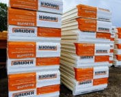
For insulation, continuity of the insulation and the tightness of the vapour control layer must be ensured. PIR boards can reduce the thickness of the build-up, but they need correct joints and fixing. Their low lambda does not remedy the thermal bridge at the wall plate. Maintaining the required ventilation beneath the covering is also important.
The sequence of flashings and sheets should follow the instructions. The eaves, roof valleys and penetrations are prepared at the appropriate moment, not as additions at the end. Swarf is removed as work proceeds and damage to the coating is protected. This helps to avoid rusty marks on the new roof.
Step 5. Hand over the roof together with the documentation
Check the evenness of the roof slopes, the stability of the flashings and the execution of the areas at the chimneys. Assess whether the roof valleys and gutters are clear. The inspection should also cover the attic and the behaviour of the ventilation inlets and outlets. Acceptance from street level allows the appearance to be assessed, but is not sufficient to check the installation technique.
Ask for the documents for the materials used, the warranty conditions and maintenance recommendations. Photographs of covered details and a schedule of the profile and coating are useful. They will make it easier to supplement the material later. Also establish who will carry out the inspection and how any defects noticed are to be reported.
A good renovation ends with a tidy site and clear information about the scope completed. Leaving the old problem beneath a new covering usually only postpones the repair. Replacing the roof is an opportunity to improve the entire build-up and prepare it for the planned use of the building.
7 branches. Materials closer to your project.