Installing sandwich panels
How do you fix sandwich panels to a new masonry wall?
A masonry wall can serve as a substrate for sandwich panel cladding, but it does not remove the need for a fixing design. The masonry must be assessed, the load path determined and the space between the layers resolved. On a new building, anchoring and openings can easily be planned in advance. This helps avoid random spacings and repairs to freshly completed façade. The type of masonry units, their strength, voids, mortar and the quality of workmanship all matter. A fixing chosen for concrete is not automatically suitable for hollow block masonry. The design must specify the loads, the substrate and the permitted anchoring solution.
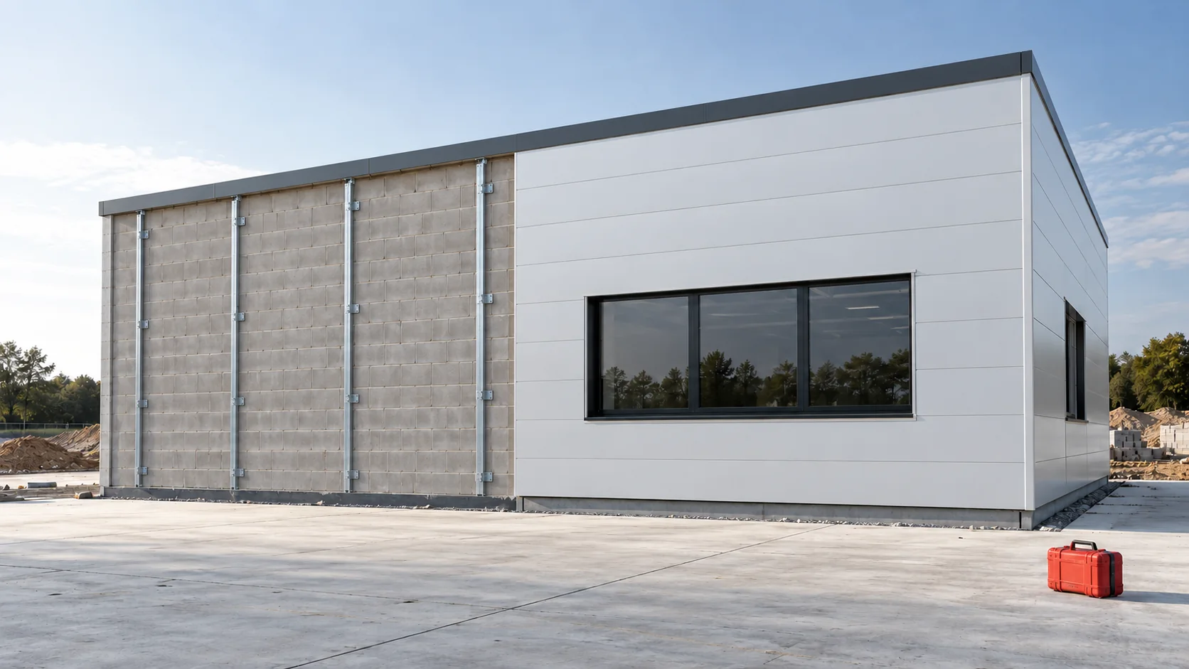
Check the masonry before selecting anchors
The new wall should meet the conditions required for installation. Its geometry should be checked, as well as the position of ring beams and lintels if they are to participate in load transfer. Where the data on the substrate is insufficient, the designer determines how it is to be verified. This is not replaced by selecting a greater number of random anchors.
Design the supporting frame and the load path
The substructure can level the plane and provide supports in line with the panel layout. Its elements, brackets and anchors must be calculated, and the offset from the wall taken into account. A greater distance changes the way the load acts on the connection; it is not merely a matter of aesthetics.
The spacing of the framing is selected for the specific panel, wind load and structural behaviour. Proper framing is needed at openings. It should not be assumed that the panel can rest arbitrarily on an uneven wall or that a wide flashing at the window will replace a missing support.
Allow for movement joints in the new masonry
Movement joints in the masonry wall should be taken into account in the enclosure design. They should not be rigidly tied by the panel or a continuous framing without analysis. Movements of the substrate may be transferred to the joints and flashings, and the seemingly smooth façade will begin to work in an unforeseen way.
The penetration point should be coordinated with the panel layout and openings. The detail should maintain the required tightness, thermal protection and capacity for movement. Where the wall meets a steel structure, differences in their deformation must also be considered. This is one of the reasons why an enclosure on masonry is a separate design task rather than simply screwing on another layer.
Assess moisture in the multi-layer wall
The wall and the metal panel form a system that requires a thermal and moisture assessment. The metal cladding has high diffusion resistance, and a new wall may contain construction moisture. The way the space between them is resolved should follow from the design, not from leaving a gap at random.
Not every such gap should be treated as ventilated. If the design provides for ventilation, its continuity is needed along with a solution for inlets, outlets and protection against water. If the system is to be sealed, other details are required. The two concepts cannot be mixed on one façade without analysis.

Put the works in a logical sequence
First set out the axes and check the substrate. Then install the designed brackets and the substructure, check the plane and the protection of the detailing zones. Before the first panel, prepare the plinth elements and seals that will later be covered.
Fix the panels in accordance with their system, maintaining the correct position of the joints. Around openings, coordinate with the joinery team to maintain continuity of insulation and water drainage. Final installation of the cover trims should take place after checking what they conceal, and not serve to hide unagreed solutions.
Calculate the cost of the additional load-bearing layer
For the example, let us assume a casing of 48 m², a panel at €38.19 net per m² and a substructure with anchoring at €16.66 net per m². The panel material would cost €1,833.12, and the substructure €799.68. Let us add an assumed €388.84 for trims and seals and €666.58 for installation. In total this gives €3,688.22 net.
The result is €76.84 net per m² and applies only to the stated assumptions. It does not include wall construction, joinery or other unlisted works. The actual price depends, among other things, on the substrate, height, number of brackets, openings and access to the façade. This is not a current commercial offer.
Check the detail at the junction with the remaining enclosure
Particular attention is required at the corner where the cladding on the wall meets the timber-frame wall. The two parts may move differently and have different support planes. The connection should remain sealed without accidentally rigidly tying together elements that move.
After completion, keep the anchoring documentation, the substructure layout and photos of the details. This makes later design of equipment fixed to the façade easier. New holes should not be drilled in unknown locations in the belief that there is uniformly load-bearing wall behind the entire panel.
Questions and answers
Can the panel be screwed directly to the wall?
Only in a solution designed for the specific substrate and panel. In many situations a subframe is required. The method of transferring weight, wind and wall levelling must be specified in the design.
Does the gap behind the panel always prevent moisture?
No. It must have a designed function and proper terminations. An incidental void is not a complete ventilated assembly and may hinder assessment of air and water flow.
7 branches. Materials closer to your project.