Flat roofs
Outlet, overflow and roof edge. How do you plan drainage for a flat roof?
If the emergency overflow is set too low, every downpour will turn into a constant spilling of water down the façade, loading the ground next to the building. That is why, before the waterproofing is installed, the overflow level must be calculated relative to the outlet level rather than chosen by eye. The outlet itself must sit at the genuinely lowest point of the roof slope – allowing for structural deflection and local unevenness – because a slight deviation will make water bypass the grating and collect beside it. These two decisions determine whether the roof will drain water by gravity or start spilling it down the wall.
Catchments and actual falls come first
Drainage planning starts with defining the areas from which water will reach each outlet. Only then can outlet diameters and positions be selected. The outlet itself must sit at the genuinely lowest point of the roof surface – allowing for structural deflection, supports and local unevenness. Even a slight deviation is enough for water to bypass the grating and collect beside it.
Falls must be coordinated with the structure and the thicknesses of the successive layers. They can be formed in the substrate or in a screed-to-falls layer, including from suitably cut PIR insulation boards. Where height is limited, the insulation's low lambda value helps preserve its thickness. However, the parameters of a variable-thickness system must be calculated – the average thickness of the pack does not describe conditions at the outlet and parapet, which later makes it harder to achieve correct falls.
Parapet: drainage through the roof or through the edge
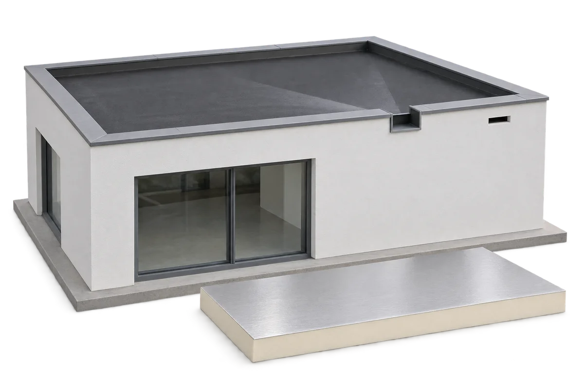
With a parapet, water can be carried away in pipes running through the roof surface or through penetrations in the parapet itself. The through-roof variant usually routes the installation inside the building, while the through-parapet solution requires a carefully detailed penetration through the edge and discharge to the outside. The choice affects the façade, the space beneath the roof and access for inspecting the pipes, so it is not purely a matter of aesthetics.
A parapet wall forms the perimeter upstand, so a blocked outlet can cause water to pond on the roof plane. The overflow height and the top of the waterproofing must follow the design, not appearance. The weight of retained water and the risk of it penetrating the interior through the lowest detail must be assessed. A correctly designed overflow has a defined discharge capacity and flow path – an opening in the parapet without checking its height and dimensions is not a complete solution.
Without a parapet: gutter and edge
At an open edge, water can be directed into an external gutter. The gutter cross-section, the arrangement of downpipes and the connection to the roofing must still be selected. A gutter set too high or waterproofing brought out incorrectly can hold water at the edge. The eaves detail and the termination of the insulation require care, because errors here are difficult to spot once the work is complete.
The overflow must not discharge onto entrances, the façade or areas vulnerable to damage. The solution should account for thermal movement of components and winter conditions. Heating of the outlet or gutter is an addition to correct geometry, not a repair for poor falls. Water must have a path even when the main outlet fails.
Gravity or negative pressure – the consequences of the choice
If a gravity system is chosen, water flows through the pipes at partial fill and with the required falls. A vacuum (siphonic) system uses special outlets and a matched installation; with sufficient inflow the pipes fill with water, and the height difference drives an intense flow. No pump is needed to create the vacuum. A siphonic solution can reduce pipe diameters and the number of downpipes and allow a collector without fall, but the whole network must be calculated.
In a siphon system, pipes must not be shortened, diameters changed or outlets added without proper calculation. In light rain the system does not have to operate at full negative pressure – it is designed with such conditions in mind. The choice between gravity and siphon affects cost and installation complexity, so it should follow from calculations rather than habit.
Failure and overflow – a plan for blockages
The design must define what happens to water during rainfall exceeding the design value or when the main outlet is blocked by leaves and debris. Emergency drainage with a defined capacity and discharge path is therefore provided. It must work even when the cause of the restriction is a blocked main drain, and direct water where it will not cause unforeseen damage.
A visible leak from the overflow may indicate that an inspection is needed, but constant overflowing during ordinary rain should not be treated as normal. The outlet flange must match the type of waterproofing, and the connection must be executed precisely. No ridges or remnants of material may be left around the outlet. On green roofs and terraces, access through suitable inspection elements is needed, and the surface layer must not cover the area requiring cleaning.
Workmanship and maintenance instead of appearances
Protective baskets must be matched to the outlet rather than replaced with an arbitrary grille that restricts flow. Once the work is complete, the entire water path must be checked and the documentation retained. Thereafter, debris must be removed and the condition of the seals assessed. Self-cleaning properties attributed to system components do not remove the need to inspect the outlets.
Good drainage combines correct calculations, careful workmanship and regular maintenance. Together they protect the roof against unplanned water accumulation. Neglecting any one of these increases the risk of ponding and costly repairs.
7 branches. Materials closer to your project.